Flow Design (previously Falcon) is a lightweight computational fluid dynamics (CFD) tool that integrates with Autodesk Revit (for building design) or Autodesk Inventor (for product design).
You can use it to simulate air speeds and pressures around a building site in Revit.
This pages provides information on how to use Flow Design in Revit. To download Flow Design, make sure you visit the Software Installation page.
- Process Overview
- This video provides an overview of the Flow Design Process. The following pages will describe each of the settings in greater detail
- Configure the Wind Tunnel
- One of the most important first steps is to set up the wind tunnel. These steps include properly sizing it and orienting your model appropriately.
- View Results with Planes
- There are a variety of ways to view your results in Flow Design. One of these ways is with planes. You can use planes to visualize a horizontal or vertical slice through the airflow.
- View Results with Flow Lines
- Flow lines are another way to visualize results. These can be useful to identify patterns and potential problem areas.
- Using the Ribbon
- You can easily change any of the settings in Flow Design from the Ribbon. This page lists all the Ribbon settings that you can access.
- Flow around Buildings
- Once you set up your simulation, you'll start to get some meaningful results. But what do these results mean? This page starts to provide some explanation in the context of buildings.
- External Flow
- Similar to the previous page, this page phrases flow design results in the context of external flow, what you’ll be evaluating in the software exercises.
Exercise:
In this exercise, we’ll look at airflow in a dense urban center. Using the standalone version of Flow Design, we will study airflow and pressure patterns around and between densely spaced tall buildings. The model below is of the Financial District in New York City, USA. It’s a simple mass model of the site.
Download Data Set (note that this is not a Revit file, it’s a .sat which can be used by Flow Design)
- Tall_Buildings-Site.zip (extract .sat file from this zip file)
For orientation purposes, here is a plan view of the site.

Follow the steps outlined below:
- When you start Flow Design, import the .sat file you downloaded above. It might take a few seconds to load.
- Immediately you’ll start to see the dynamic airflow. Before you start to interpret results, let’s make sure you are using the correct settings.
- a. Simulation Settings
- Simulation Resolution = 100%
- Model Dimensions = Feet
- Display = whatever you are comfortable with
- b. Wind Tunnel Settings
- Wind Speed = 15.2 ft/s ; 4.6 m/s
- Size your wind tunnel using best practice specifications
- c. Model Orientation
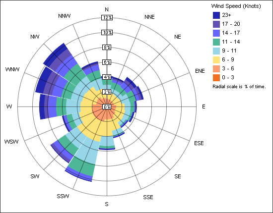
- Z Angle = 45(this will simulate winds that come from the NW)
- d. Leave the simulation as 2D. A 3D simulation would be more accurate, but requires more computing power
- e. The rest of the settings (velocity or pressure, plane or flow lines, shaded or vectors, and top or side) can be changed based on your preferences and what the questions below are asking. If you need help configuring, see our Flow Design Resources
- a. Simulation Settings
- Play around with the settings mentioned in e as well as the plane elevation. The questions below will require the settings described in a-d, but how you visualize results is up to you.
- It’s likely that your simulation status will remain at “Transient” for a while. This is okay. Typically you want to see your simulation “Stabilize,” which means the flow has reached a steady-state condition and the results are no longer changing. Sometimes though based on the design you are analyzing, it’s not possible to get stabilized results. This might be because there are vorticies or other recirculation regions. For this exercise, let the simulation run for a few seconds until regular patterns start to appear, then you can start interpreting the results.