You are here
The Math Behind CFD
Truly understanding fluid flows has perplexed people for millennia. Although Archimedes began mathematically describing aspects of fluid mechanics in 250 BC, the governing equations are still somewhat poorly understood. With the complex math involved, it remains essentially impossible to predict fluid behavior by hand for all but the most basic situations.
Because of this complexity, designers often rely on experimental set-ups like physical prototypes and wind tunnels. While these methods are generally useful, they are often very expensive and can be limited in the type of results they provide. Computational fluid dynamics simulations yield design insights, and allow faster design iteration, without needing as many physical prototypes. Regardless of how you test and optimize your design, understanding the basics of fluid mechanics is essential.
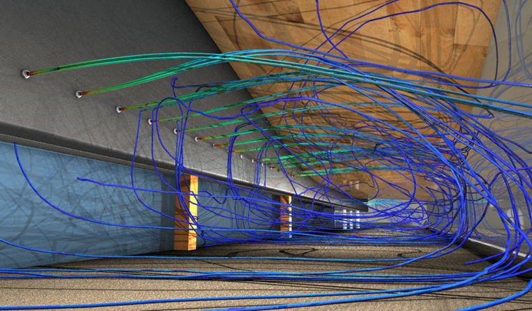
Testing this cooling system for an airport would likely be unfeasible without CFD
The mathematical understanding of fluid dynamic principles is beyond the scope of this website, and is best achieved through a dedicated university-level class. Additionally, for some applications, a strong knowledge of heat transfer may be necessary. If you would like to explore these topics the math is discussed in depth both on the Autodesk WikiHelp pages and at cfd-online.com. You will especially want to acquaint yourself with the Navier-Stokes equations, which are the governing equations that describe the motion of fluid flows.
The Concepts Behind Fluid Mechanics
We will however cover the basics metrics of CFD, specifically velocity, pressure, density, and others which can all be used to develop an appropriate design. Additionally, the difference between laminar and turbulent flow is of great importance in many applications.
Velocity
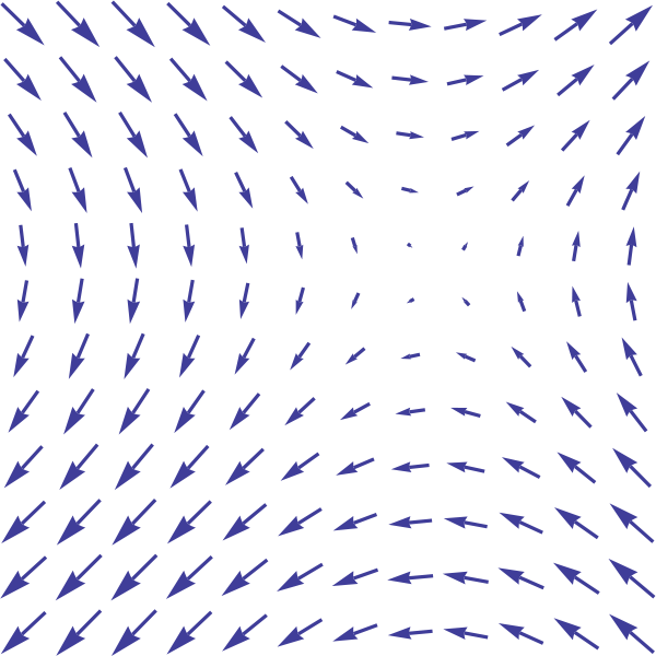
Velocity is the rate of change of position of an object or particle, or mathematically v = Δd/Δt. Velocity is a vector quantity, meaning that it has both direction and magnitude. In other words, velocity describes both how quickly an object is moving, as well as the direction in which it is moving. These vectors can be graphically represented in a vector field, which is a very useful and intuitive tool for visualizing fluid flows.
A portion of the vector field (sin y, sin x) (wikicommons)
Pressure
Another key aspect of fluids is their pressure. As in solid mechanics pressure is the ratio or force to area, or mathematically p = F/A. Fluid pressure can be found at any point in a fluid, but may be a bit less intuitive, however.
In fluids, there are two situations that affect pressure differently. The first is known as static pressure. An example is open channel flow. This is essentially flow that is not fully bounded by solid constraints and has negligible velocity. For example, the very slow flow of water through a canal is open channel flow. The mathematics for this are fairly complicated, but for incompressible fluids (such as water) with constant density, the pressure of an open channel flow can be approximated by the hydrostatic pressure, which is calculated as p = ρgh+p_atm. This says that the pressure at any point in the fluid is proportional to the depth. It is simply the density of the fluid times the acceleration of gravity times the distance below the surface all added to the atmospheric pressure. This also means that the increase in pressure from the fluid is linear as you descend through the fluid. If you double your depth, you double your static pressure; if you triple your depth you triple your pressure, etc., excluding the atmospheric pressure.
The other kind of fluid pressure occurs in moving flow, such as in a gas line or a pipe. For simple flows, include the dynamic pressure of the flow, or the pressure created by the movement of the fluid itself. The dynamic pressure of a fluid is given as p = (1/2)ρv^2. From this we can get the entire pressure of the fluid at any given point as p = p_atm + ρgh + (1/2)ρv^2. However, this only accounts for ideal fluids, which have no viscosity and are only theoretical. In real life, fluid pressure in a pipe is affected by many other aspects, such as the effects of friction and viscosity. The mathematics that describe this are even more complicated, and will not be discussed here. Thankfully, CFD takes into account these additional aspects and calculates accurate pressure in complicated flows.
Density
Density is simply the amount of mass in a given volume. This is given mathematically as ρ = m/V. Additionally, for an “ideal gas,” which is a good approximation of many gases under normal conditions, you may calculate pressure (P) as the product of density (ρ), the specific gas constant (R), and temperature (T). This law is known as known as the “ideal gas law” and is written P = ρ*R_specific*T. From this we can see that as temperature increases the density decreases, while as external pressure increases density increases.
Often, densities will be are quoted at STP, meaning standard temperature and pressure. Different scientific bodies unfortunately sometimes use slightly different temperatures and pressures for their measurements, so these should be checked to ensure consistency.
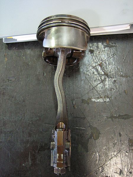
It is also important to note that the density of a fluid (especially gasses) may be strongly affected by external pressure. For example, pumping up a bicycle tire greatly increases the density of the air in the tire, as significantly more air is contained in the same volume. Some fluids are known as incompressible, meaning that changes in pressure do not affect their density. Examples of incompressible fluids are water and hydraulic oil. For example, no matter how hard you push on water it does not compress. In fact it is possible to break steel connecting rods in an engine by getting water in the cylinders, which doesn’t compress and instead bends or breaks the connecting rod in a situation known as hydrolock.
The power of incompressible fluids (wikicommons)
Steady State vs. Transient Flow
Simply put, the difference between a steady state flow and a transient flow is that steady state flow will not change if the conditions remain the same, while a transient flow will. The definition of not changing means that no aspects of the flow field will change and that pressure will remain constant, among other considerations. It is quite possible for a transient flow to settle into a regular pattern, but this is not considered a steady state flow. One example of this kind of transient flow is known as a von Kármán vortex street. The Autodesk Simulation Workshop has videos on setting up both steady state and transient flow models.
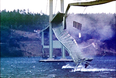
Many engineering problems attempt to optimize steady flows, such as the flow of air through a pipe. However, there are some very important and interesting unsteady flows in nature, such as aeroelastic flutter, which is strong enough to bring down bridges but may also be used for future energy generation.
The collapse of the Tacoma Narrows Bridge was due to aeroelastic flutter (wikicommons)
Laminar vs. Turbulent Flow
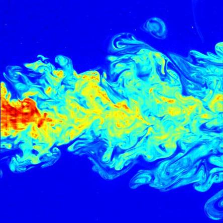
In the most basic terms, laminar flow can be thought of as being “smooth,” while turbulent flow can be thought of as “chaotic.” More specifically, laminar flow is when a fluid flows as streamlines that do not mix or dissolve into a complex jumble. The term “turbulence” lacks a clear, concise, and agreed-upon definition, although it is generally easy to identify. Turbulence is the condition of chaotic looking fluid flow that changes drastically given even small perturbations. It is unknown if turbulent flow is truly random due to some open mathematical questions, although it is suspected that turbulence is in fact a unique result of the underlying fluid equations and inputs (that is to say that the equations and inputs could theoretically be used to exactly solve for turbulence). Unfortunately, as turbulent flow is extremely sensitive to minute changes in boundary conditions it may not ever be calculable for real-life situations. Despite this, turbulent flow can be modeled to find a statistical average behavior which is useful in many situations.
A beautiful example of turbulent flow (wikicommons)
It is important to understand that most physical flows in engineering applications are turbulent. The threshold between laminar and turbulent is quite low. That is to say that flows often transition to turbulence easily and often at very low flow rates. Also, turbulent flow can appear to have streamlines that are not “jumbled,” but because of the flow velocity, the flow is turbulent.
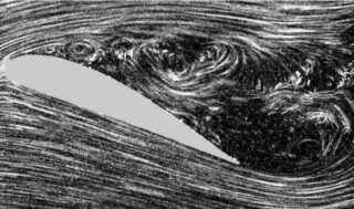
Another way to characterize turbulence is by how much energy it transports. Turbulent flow is generally much more energetic, and can transfer more heat than laminar flow. Additionally, it generally has more favorable aerodynamic properties, and designers often induce turbulence to reduce drag. An example is the flow over a golf ball. The dimples serve to induce turbulence so that the flow stays close to more of the ball. If the flow was laminar, it would separate sooner, and the wake would be bigger. Turbulence causes the wake to be smaller, which reduces drag, which allows the ball to fly further. However, in certain cases turbulence can cause serious aerodynamic problems. For example, if a wing flies through the air at too high of an angle flow separation will occur, resulting in a turbulent region behind the wing and causing the wing to lose lift and stall.
A turbulent region behind a wing, resulting in greatly reduced lift and increased drag (wikicommons)
Compressible vs. Incompressible Flow and More
For many other definitions of fluid flow attributes please refer to this Autodesk WikiHelp page on the subject. It gives good information on a variety of topics that are out of the scope of this website, including such areas as bondary layer flow and many thermal areas of interest.

