You are here
The next step in running effective FEA is defining the details of the simulation and appropriate meshing. The first part of this is the establishing of what kind of simulation you are looking to run.
Determining the Analysis Type and Setting Analysis Parameters
This guide on Autodesk Wikihelp is a good start for determining the kind of analysis to use. In general, “Linear” analysis is used with common engineering metals and plastics within the elastic region on the stress-strain curve and “non-linear” analysis is needed when you’re using materials like rubber or going beyond the yield strength and causing permanent deformations with other materials. You can do simple linear analyses in Autodesk Inventor and you’ll need Autodesk Simulation 360 for nonlinear analysis.
This step also includes assigning appropriate materials for the parts in the simulation, and selecting analysis parameters, such as the desired factor of safety.
Setting materials in FEA
The Art of Meshing
Next, you must appropriately mesh the model. Meshing is the process of breaking up the model into smaller pieces that can be solved by the software using advanced matrix math and then merged together to show the correct result for the whole.
Meshing is in many ways more of an art than a science. The goal is to create a mesh that accurately represent the stresses and displacements that will be present in the real life application of a part, without taking up too much computing power and time. This balance is a tough one to strike. New users will often greatly under- or over-mesh, or rely entirely on the automatic mesh provided by the software.
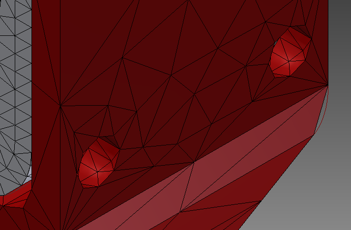
At this point, a standard practice is to apply an automatic mesh. This means that the program calculates what it thinks is an appropriate mesh, given the geometry of the part. This mesh is often not ideal for the problem, due to the computer lacking any real engineering judgment, and requires what is known as mesh refinement. This means simplifying and creating a “coarse” mesh in areas you’re less interested in, and creating a detailed “fine” mesh in areas you’re most interested in studying (where failure is most likely to occur).
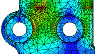
Automatic mesh vs. locally refined mesh
This refinement is important because it allows the software to more accurately model localized stress concentrations. As the mesh becomes finer, the software generally gives a more accurate result (although there are problems that may occur that will be discussed below).
Additionally, there are many different ways to mesh a part, resulting in different kinds of pieces, known as elements types. Using the right kind of element is important, as they all have different properties and applications.
Perhaps the most common error in the realm of defining analysis details is simply using the wrong kind of analysis. For example, this could take the form of using static analysis instead of dynamic analysis for impact tests of solids, or not considering the effects of heat or fatigue in static loading situations. Properly understanding failure modes and defining and using the correct form of simulation is critical in getting a useful output from the software.
Avoiding Meshing Errors
Both over-refining and under-refining your mesh can lead to incorrect results when a user does not understand the finer points of meshing. By understanding the basic principles of FEA, these issues can both be understood and avoided.
Avoiding over-refining your mesh
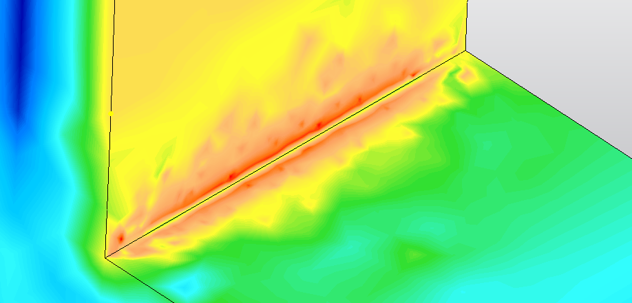
Getting incorrect results from using too fine of a mesh seems counter-intuitive. However, it is a result of the basic idealized mathematical equations used by FEA, and how they are solved. For example, if there is a totally sharp interior corner (known as a “reentrant corner”) on a piece (the inside corner of an L-shaped member for instance) the theoretical stress at that point is infinite. In reality, the piece would either contain a radius or quickly deform to reduce this stress. However, when analyzed with a linear-elastic simulation, the stresses will continue to increase as the mesh is refined. This error can be resolved by applying a radius to the original part. For a good example of this error, refer to this website on Stress Singularities.
A view of a stress singularity at a reentrant corner
Avoiding under-refining your mesh
Alternately, errors can occur because of an under-refined mesh. You need a more detailed mesh where stresses are likely to concentrate. This is often the case around holes, notches, or corners in parts.
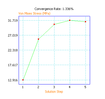
Mesh refinement should often be done locally in areas of interest, as refining the mesh of a large part will greatly increase calculation time. The mesh should be refined and the test rerun until the stress results converge on a single result. This indicates that the results are correct, assuming the analysis was set up correctly. A good example of how to run convergence testing can be found here.
An example of a convergence plot
There are many other common pitfalls when it comes to meshing an FEA model (several of them are spelled out in this Machine Design article). It is important to understand the FEA software to avoid these errors.


