Inventor

3D CAD and Simulation for Mechanical Design
Autodesk® Inventor® 3D CAD software products offer a comprehensive, flexible set of software for 3D mechanical design, product simulation, tooling creation, engineer to order, and design communication. Inventor takes you beyond 3D to Digital Prototyping by enabling you to produce an accurate 3D model that can help you design, visualize, and simulate your products before they are built. Digital Prototyping with Inventor helps companies design better products, reduce development costs, and get to market faster.
Autodesk® Inventor® 3D mechanical design software includes CAD productivity and design communication tools that can help you reduce errors, communicate more effectively, and deliver more innovative product designs faster. The Inventor model is an accurate 3D digital prototype that can validate the form, fit, and function of a design as you work and unites direct modeling and parametric workflows so you always have the right tool for the job.
Inventor can help you:
- Integrate data from AutoCAD® software and 3D data into a single digital model and create a virtual representation of the final product
- Streamline projects that require opening third-party CAD data
- Improve productivity by automating repetitive design workflows
- Better collaborate with accurate 2D documentation and 3D visualization tools
- Efficiently and securely exchange design data with integrated Autodesk® Vault data management software
- Manage associated business processes with new Autodesk® PLM 360 product lifecycle management software
- Optimize material selection based on environmental impact, cost, and performance to make better sustainable design decisions
Software
It is important to understand your sustainability goals before using FEA. There are many aspects of sustainability that can be investigated, but the overarching aim for all of them is to reduce the impact of your product.
Interpreting the results is the key to properly utilizing a well done simulation.
Make sure that you have the time allocated to run the simulation on your computer. Some programs will allow you to alter the solution settings, such as which solver to use and whether do solve iteratively, so make sure these are correct.
Loads and constraints must be applied after the analysis type is selected, the basic parameters like materials have been set, and the part is meshed.
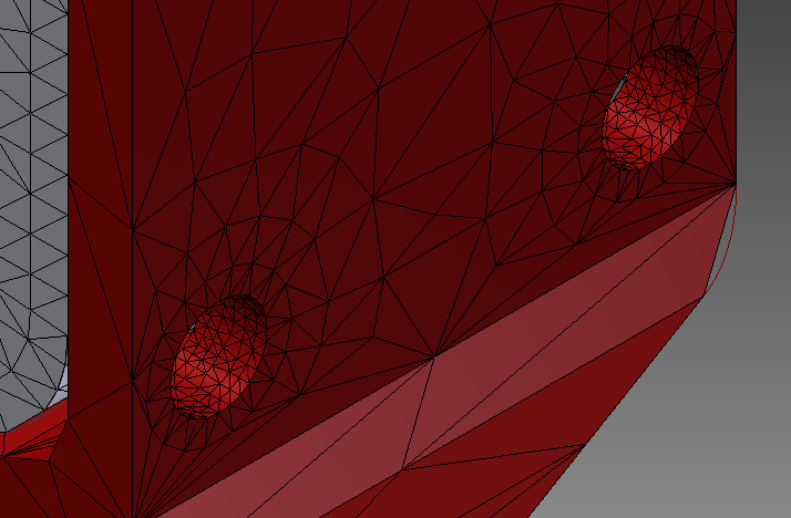
The next step in running effective FEA is defining the details of the simulation and appropriate meshing. The first part of this is the establishing of what kind of simulation you are looking to run.
Pages
Project Gallery Examples
Chinese students from Tongji University use FEA in Autodesk Inventor to help lightweight the aluminum and carbon-fiber frame of their ultra-mileage electric vehicle. The result is a car that weighs 55 kg (120 lbs) and can travel 347 kilometers with one kilowatt hour of power (7,250 MPGe).
Ventive S is a passive heat-exchanging ventilation system designed for easy home retrofits to increase ventilation while lowering heating requirements.
In 2011, students from Stanford University were awarded a grant to develop solar-charging stations for the developing world. Learn about their process and their final result.
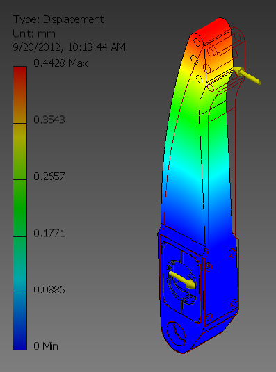
An ultra-light airplane manufacturer, Air Creation, identified their steering pedals for FEA optimization. They were able to reduce mass, embodied energy, even the cost of the part.
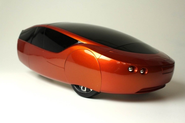
The Urbee team was able to use an integrated approach to produce a fuel efficient vehicle that achieves around 150 miles per gallon and weighs only 1,200 pounds.


