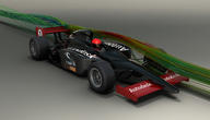
The Ventive S System is a passive heat-exchanging ventilation system designed for easy home retrofits to increase ventilation while passively lowering heating requirements by preheating incoming air, saving the occupants money and reducing carbon emissions.
The Ventive technology can easily be installed in an existing chimney in under an hour without costly renovations. Tom Lipinski, the head of green structures, and his engineering team, used Autodesk software to optimize the cowling and heat sink to create the right amount of airflow and heat transfer to allow for ideal air circulation without the standard associated cooling.
Autodesk Software Used:
Green Structures, a British company that works on sustainable home renovation, has developed a unique passive strategy for home ventilation.
Their result is a product called Ventive, designed with chilly British weather and old houses in mind, which could drastically reduce heating costs and energy, reducing emissions and helping to save people money.
The Problem with Retrofitting
Retrofitting existing buildings is extremely important in the United Kingdom, where approximately 1/3 of all buildings are over 100 years old, and 80% are expected to still be standing for another 40 years. The UK government has stated that they are aiming for an 80% reduction in emissions by the year 2050.1 However, since 45% of all energy used in the UK is used by buildings2 there will have to be a great deal of improvement will have to be made on existing buildings to hit this mark.
Heating: The Problem with Cold Weather Ventilation
Ventilation is an important part of any building. Not only can it keep occupants cool when the weather outside is warm, it is required to prevent the buildup of carbon dioxide, volatile organic compounds (VOCs), and other pollutants that naturally collect inside of a building. In fact, there are specific building codes for the amount of ventilation that is required for new buildings. The introduction of clean outside air is therefore important even in the winter, when outside air is too cold to be introduced into the building directly. This problem is often solved by simply heating the air in the building, which is costly and causes carbon dioxide emissions. By reducing the need to heat the air great savings can be achieved, both environmentally and economically.
Current Fixes
There are currently systems on the market that can help reduce these heating costs by using some of the heat from the outgoing air to warm the incoming air. These systems are known as Mechanical Heat Recovery Ventilation (MHRV) systems. These systems work by pumping cold outside air past a heat exchanger and warmer exiting inside air. This air is then introduced to the building. While this system does save on the amount of energy consumed by the building there are still multiple downsides. First, these systems are costly to set up and require the replacement of expensive air filters. Secondly, as they require energy to run they offer only limited reductions in emissions. Finally, they are difficult to install, and therefore are not good for retrofitting existing buildings, especially old homes.
Figure 1: A Mechanical Heat Recovery Ventilation system. Note that it requires extensive ducting and is quite large.
The Solution
Looking at these problems, Tom Lipinski, who has a background as a building retrofit architect saw a great space for new technology to provide a solution. He looked at the existing infrastructure of old buildings, such as chimneys and fire places, that should be worked with, rather than against.
Figure 2: Ventive is very easy to install in the existing chimney system, saving time and money
From these investigations he was able to come up with his first idea. This concept was for a mechanism that would take advantage of the natural ducting of chimneys to help direct outside air into the building, and would utilize a heat exchanger to pre-heat the outside air, keeping the interior of the building warm.
Design Requirements
The first year and a half of the 2 ½ year product development was mainly basic research and initial design. During this phase the group developed an understanding of the environment in which their product would have to operate. Their first constraint was the fact that wind in an urban environment can fluctuate greatly in both direction and speed. This meant that the heat exchanger would have to be omni-directional, as well as operational over a large range of wind speeds. The flow out of the house would travel in a tube up the middle of the heat exchanger, while the outside air would flow down the sides around it. They also determined that the heat exchanger would have to work with:
- A minimum amount of pressure drop across it, to minimize head loss and maximize flow
- A minimum boundary layer, to maximize heat exchange
- The largest heat-exchanging surface area possible
While these constraints helped determine the design of their heat exchanger, they also had to worry about how their design could get the best air flow possible.

Figure 3: The Ventive heat-exchanger, designed with the above requirements in mind
How the System Works
The Ventive team used two major principles to guide the design of their roof cowling and optimize air flow. The first of these is the natural buoyancy of warm air in the form of a passive stack technique. As outside air in the UK is usually cooler than inside air, the warm indoor air will naturally float up and out of the chimney while cool, denser air will flow in to take its space. The greater the difference in temperature, the greater the effect. The openings within the house also help to drive the effect, as air inlets are installed in the base of the fireplaces and outlets at the tops. This orientation allows the cool, dense air to flow into the bottom of the room while the warm, buoyant air exits at the top.

Figure 4: Ventive takes advantage of differences in air density within each room
The other technique they used was much more esoteric and was quite complicated to model. To optimize air flow through the system due to wind they designed the top of the cowling to work somewhat like an airplane wing. With wind speed above 1.5 m/s (which is below the range at which people can feel any movement) the cowling draws in air using the Coanda Effect, a complicated fluid dynamic principle. The rate of air flow through the system increases as wind speed increases until, at high speeds, the cowling begins passively throttling the flow rate to avoid discomforting breezes.
Figure 5: This simulation shows flow coming up through the center of the Ventive system, while flowing down the wind facing side, as required.
Finally, the heat exchanger is based on a countercurrent model, rather than a concurrent flow model. In a concurrent flow exchange, the hot and cold fluids travel in the same direction, eventually reaching the same temperature. In a countercurrent design, it is possible for the hot and cold fluids to exchange almost all of their energy, nearly flipping their temperatures by the end of the exchange.

Figure 6: Concurrent and countercurrent exchange mechanisms.
The magnitude of the property to be exchanged, is represented by shading. The direction of transfer across the barrier is from the greater to the lesser magnitude. (Diagram and caption from Wikipedia)
The effect of the combination of a unique heat exchanger and countercurrent exchange system is a design with over 90% efficient heat exchange while supplying a great deal of air flow to a house. This means that given a 10 degree difference between the outside and inside air temperature, the incoming air would only be 1 degree cooler than that already inside, greatly decreasing the amount of heating necessary.
Simulation for Analysis and Optimization
Throughout the detailed design phase the team used Autodesk tools to help produce over 200 digital prototypes. These prototypes were tested using Autodesk Simulation CFD analysis and tweaked in Autodesk Inventor to optimize their properties. Following the design they were turned into physical prototypes and tested in a mock-room setup by Imperial College London. The Ventive system was also digitally rendered in Autodesk Showcase to help receive hundreds of thousands of dollars in government funding and prize money to help with the development costs.
Figure 7: A version of the Ventive design in Autodesk Inventor
The Current Status of Ventive
The first model of the Ventive passive heating ventilation system is currently available for sale and the company is working on 2 new products as well. One of these new products is designed to work on humidity extraction, while the other is a commercial model of the currently existing product designed for a flat-roof environment.
Figure 8: The Ventive S System being installed on a house in the UK
Even with the current success of his company, Tom Lipinski is not content to remain still. He believes that the best way of staying competitive in the market is not patents, but continued innovation, and “Autodesk products allow us to stay ahead,” he says.


