You are here
Loads and constraints must be applied after the analysis type is selected, the basic parameters like materials have been set, and the part is meshed.
The accuracy of the loads and constraints in an FEA model has a huge impact on the accuracy of the simulation results.
Loads
Loads are fairly simple to understand. They are the applied forces that will occur during the use of the product. To accurately understand potential failure modes, these should be set as the largest expected loads that the product could see during its lifetime, rather than the average loads.
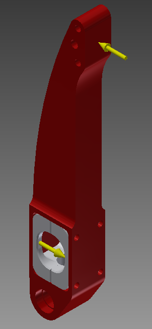
Loads applied to a part in FEA
To get accurate results, you need to ensure that the loads you apply acting on the most appropriate surfaces, or sections of a surface. Properly assigning loads and is obviously a very important part of simulation. Considerations such as the surface, or section of a surface, on which a force is acting can greatly affect the final outcome.
Constraints
While loads act to set a part or assembly in motion, constraints limit this motion (translation, rotation, or both). In statics, this is known as limiting the degrees of freedom.
Time and effort should be taken to ensure that a part is constrained in the program as it would be in real life. Constraints are applied at either a point or a surface and must be considered carefully. It is often easiest to simply say that some face will remain fixed, but this will often give unrealistic results if the real world constraint method differs.
Constraint applied to a part, in the FEA tree
The user must use good engineering judgment to properly apply loads and boundary conditions to get accurate results from the software. Over or under-constraining the model can provide essentially useless information. However, using the correct number of constraints but in the wrong places or combinations can be just as bad. An excellent example of the effect of misapplying constraints in FEA can be found in this article by Chris Hall at Value Design Consulting.


