You are here
Before doing anything, estimate results
The first step in the analysis workflow is an important, but often overlooked one: estimating results.
It is important to have a good idea of the expected stresses and deflections before beginning the computer analysis, as it gives the ability to “sanity check” the results. If they cannot possibly be true, then the user should investigate the analysis to see where the error is coming from and correct it. If some sense of intuition is not used on the part of the user, it is easy to believe convincing-looking results in FEA that are totally incorrect through human error or software issues.
Another issue is using FEA when it is unnecessary. For many simple problems the results can be found in common engineering handbooks (such as the deflection of a simply loaded cantilever beam), and these results are guaranteed to be accurate if used when applicable. This eliminates the need for FEA in certain cases.
Machinery’s Handbook is an engineer’s best friend
Choose the appropriate modeling tool
The next step in running any analysis is to build a model of your design. There are many modeling tools and approaches, and each offers benefits and downsides.
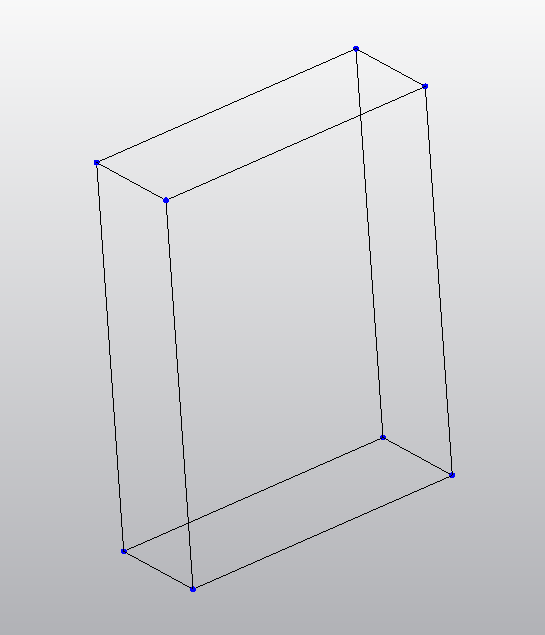
For simple models, it may be wise to create your model in whatever analysis software you chose to use, as many have simple modeling capabilities that are quick, optimized for producing geometry that can be simulated, and do not require porting information between programs.
A simple model in Simulation Multiphysics
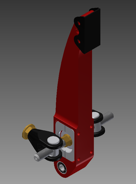
More complex geometry and detailed analyses require more robust modeling software, however. In this case, programs such as Autodesk Inventor or Autodesk Inventor Fusion should be used. These programs make it possible to accurately model practically anything you can imagine.
A more complex model created in Inventor
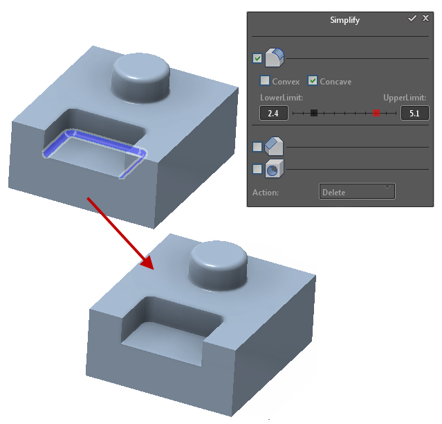
It’s important to know how detailed your model needs to be to produce useful analysis results. If the model contains excessively detailed geometric features that will not affect the strength of the part (such as slight indentations from decals or accurately modeled tapped holes), the mesh will take these into account. With these small features the mesh will be needlessly complex and take far too long to run, if it will run at all.
A way around this problem is known as model simplification. This simplification, if done well, can greatly reduce the amount of time required to run an analysis, while still yielding accurate results. The pitfalls of oversimplification will be covered in the meshing problems section, and these can be quite severe.


