You are here
Autodesk® Inventor Professional and Autodesk® Simulation Multiphysics both use FEA to simulate complex engineering problems.
For those without a lot of simulation experience, it is strongly recommended to start with the simulation tools in Inventor. Inventor uses FEA to perform basic linear static stress analysis. It also has simplified frame analyses based on beam elements. It is easy to establish loads and constraints in Inventor and quickly simulate your design at any time during the CAD modeling process.
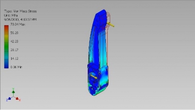
FEA Results in Autodesk Inventor for a brake pedal.
For those looking for more precise simulation results or other types of analysis, Simulation Multiphysics can perform both FEA and CFD simulations for more complex engineering problems, like stress analysis on non-linear materials, simulations that involve large deformations, and combined heat and fluid flow simulations.
For videos on Autodesk simulation technology, check out this Autodesk YouTube channel! Both Inventor 2012 and Simulation Multiphysics 2012 can be downloaded by students for free at the Autodesk Education website!
Running Simulations on Your Designs
FEA simulations begin by developing a mesh from the CAD model and end with a visualization of your results. When you mesh a model, you are dividing it into small surfaces or volumes called elements, which make up the entire mesh. These elements are all inter-connected, and allow you to apply boundary conditions and loads which can then propagate throughout the mesh. The smaller the elements, the more accurate your simulations will be; but the longer they’ll take.
You need to understand the accuracy that you require to use simulation software efficiently. It’s more effective to make changes early in the design process, so very simple geometry is often best for fast design and simulation iterations. To more carefully validate a final design, you’ll want to be much more precise about the mesh and the applied boundary conditions and loads. It is also important to remember that simulations are only an approximation and the computer model never matches reality perfectly. (See this article from Mechanical Engineering Magazine on FEA results credibility).
Simulation Workflow
Diving into your first computer simulation using CFD or FEA can be daunting. Luckily, there are plenty of resources available to help guide you towards a successful simulation model. Here is a workflow list on the basic steps to a CFD or FEA analysis:
- Build/Mesh a Model – To ensure the simulation will run and give meaningful results, it is vital to verify that your existing CAD model will mesh. Some common meshing problems might arise due to assembly interferences and unnecessary model complexity, like fillets. Simulation software will provide recommended mesh settings which can be refined based on the accuracy required for your simulation.
- Define Analysis Details – After you have ensured that your model with mesh, select the type of analysis that you would like to perform (i.e., fluid flow, thermal, thermal with fluid flow, etc.). For help selecting which type of analysis to use, see the WikiHelp section on “Which Analysis to Use?”
- Define Loads and Boundary Conditions – Set up the environment in which the design is being tested. Let’s say that you are performing a multiphysics simulation involving thermal and fluid flow effects in order to optimize your computer chip heat sink’s cooling ability. To set the boundary conditions to run the simulation, we would add the initial temperatures, where heat is being generated, and air speeds.
- Analyze Model (Solve) – Once the boundary conditions are set, all that needs to be done is to tell the program to run. This process lasts from a few minutes to many hours. Make sure that you have the time allocated to run the simulation on your computer.
- Interpret Results – Simulation Multiphysics allows you to capture animations of your simulation for a visual display of your results. Learn how to create these helpful visuals from the following WikiHelp section. A good rule of thumb for interpreting results is to find the location of the extreme result values in your simulation. From here, use your engineering judgment to decide if those values can and should be reduced. Some of the tools available for interpreting results are further explained in this article.

